For that purpose, I don't really have a synopsis for my challenge, but will
take on tasks as they come. Well, that is pretty much the same approach as I've
had in the past few years so in that respect nothing has changed.
- January 3, 01:30 (GMT+1)
-
A couple of months ago, I rescued a half dozen supposedly working
gamepads for PC compatibles. The source from where those came have several
shipping boxes of new-old-stock PC gamepads and ditto joysticks in original
boxes, but these pads were loose and thus ready to be recycled, as it is hard
enough to offset (or even donate) new-in-box gamepads. Had those been for any
game console, it had been a different story but retro PC gamers are not so
many it seems.
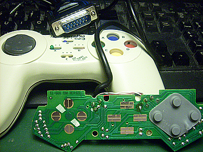
My thinking was that these pads should be possible to modify and reuse for
some other system. However I soon realized the digital pads appear to have a
load of funky electronics that converts the signals into analog signals,
possibly some serial protocol if I understood it correctly. It means that for
most systems that I'd like to use those controllers on, I need to figure out
where to literally hack the PCB. There are some 3-4 different designs of
gamepads in my lot, most or all by Logic3, but internally of course they're
pretty much similar.
One of the systems for which I want to create new controllers is my Sord/CGL
M5. I have exactly one gamepad, but I'm not terribly fond if it. This system
uses 6-pin mini-DIN with some controlling scheme resembling a matrix, meaning
four pins for the directions, of which two pins double for fire buttons, and
the other two pins for common: direction or fire. And there are diodes to
prevent the electricity to go backwards. Oh well, perhaps I didn't explain that
very well, but I have a principle idea on how it works and after taking apart
the original gamepad I've seen it implemented too.
The primary goal is to figure out where to add diodes to the PC gamepad,
which traces to cut and where to solder wires off a 6-pin mini-DIN cable in
order to convert it to M5 use.
- January 3, 23:00 (GMT+1)
-
Now all the previous components and wires are soldered off the
circuit board. They weren't that many to remove, just eight resistors, three
capacitors, two transistors, one 555 chip, four links and the eight wire cable.
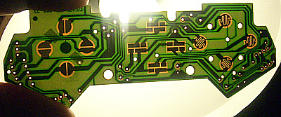
Next up is to follow the traces to see where the wires from the mini-DIN
cable should be connected to this circuit board.
Initially I planned to reuse the cable from a broken PS/2 keyboard, but soon
I realized that both PS/2 keyboards and mice only use four of the six
wires, so most cables would not carry more wires than required.
Also, as the connectors on those cables tend to be moulded, I need to get
a few solder ready connectors and take on the nightmare to solder new cables
onto the connectors themselves.
Another idea is of course to use the existing cable and wire up just a few
directions. After studying pinouts, I came to the conclusion that I should be
able to get the directions up, right, down but no fire butttons with my current
setup.
| | Pin | Colour | PS/2 Keyboard |
Sord M5 Joystick |
|---|
 |
1 | White | Data | Up / Button B |
| 2 | | N/C | Left |
| 3 | Black | Ground | Right / Button A |
| 4 | Red | +5V | Down |
| 5 | Brown | Clock | Direction common |
| 6 | | N/C | Fire common |
Now let's see if I can get anything meaningful out of this.
- January 4, 02:00 (GMT+1)
After a couple hours of soldering three diodes and four
wires (yes, it is sadly true), I was ready to try this modified gamepad. Since
the Sord M5 is a rather obscure/rare computer, the number of online resources
are very few. Add to the fact that out of the three different BASIC versions
released for this computer, only BASIC-G (Graphics) seems to handle joystick
input. The one supplied with the computer (BASIC-I for Integer math) neither
handles graphics, sounds or inputs in any favorable way, so in that way it is
no better than the e.g. the often blamed Commodore BASIC which also didn't have
any built-in commands to handle those VIC and SID chips. Even the most advanced
version BASIC-F for floating point math, doesn't seem to handle joysticks,
although it may have commands for drawing graphics for those nifty graphs.
Anyway, I realized that I've got BASIC-G complete in box (and present on my
multicart for this machine, which is the one I most often use) so it was just a
matter of digging out the manual and read up on how to handle joystick input.
It turns out joysticks and keyboard input preferrably is handled through
interrupts, accessible from BASIC so our test program looks like this. Notice
that in BASIC-G, all keywords are written in lower case while variable names
and similar are in upper case, which is kind of the opposite of how many other
BASIC versions tend to keep keywords and variables apart.
10 on joy gosub $JOY
20 joy on
30 goto 30
50$JOY
60 J=joy(0)+1:print J
70 return
Although I didn't take a screenshot to prove it, the gamepad works just like
I expected it to: it detects movement to the up, right and down, but nothing to
the left as I haven't connected anything to that pad. Also the various fire
buttons so far are left unconnected.
So this means now I need to order or locally buy some 6-pin mini-DIN
connectors and wire those up fully, in order to create one or two gamepads
for Sord use. Well, at least a bit of success in two days of work!
Actually I started a different project three years ago, with building an
adapter board that would let me plug in Atari style joysticks, but due to the
matrix like design, the adapter would need some CMOS chips that in their turn
need a power source, e.g. a 9V battery. I did some soldering work, but then
abandoned the project for being a bit too complex. It is possible that I have
a look at it again, although the idea of reusing PC gamepads seems far easier,
and as long as one can have fully working ones for free, it is just as good.
- January 6, 01:30 (GMT+1)
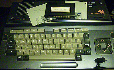
Eight years ago, I bought myself a Philips VG-8235/00 MSX2
computer. While it works OK, the floppy drive that once was replaced is only
operating as single sided, despite the mechanism itself is a 1.44 MB one.
Over the years, I've read many DIY guides on how to make it double sided,
including various cable designs, how to get side select signals from the
external drive connector to the internal ones, internal mods and of course how
to replace the DOS ROM to a version that will recognize double sided drives.
Sorry to say, despite I did this once again, it still only handles 360K
disks which is a pity as most software seems to expect 720K disks. Whoever
originally installed the floppy drive soldered every wire directly to the
floppy drive PCB, which makes it even more difficult to troubleshoot how it
is wired up. Hopefully I'm reasonably close to fixing this, so I finally can
get this eight year old modding project finished.
- January 10, 21:20 (GMT+1)
-
While I haven't made any progress on making the floppy drive
double sided, at least I figured out how to mount single sided 3.5"
floppy disks on a PC in Linux. Or rather, if I try to mount a such disk, the
PC drive makes a lot of noise and takes a lot of time to read it. Furthermore
I spent two whole evenings trying to put individual files to the disk and get
them to work properly on the MSX side.
Eventually I realized the method that works is to create disk images, which
can be mounted loopback as devices on the Linux side, store individual files
onto the image and then write back the entire image to a custom generated
single sided device, mknod fd0u360 b 2 12. It
might also be possible to alter the disk ID on the single sided MSX disks to
make them behave better in Linux, but so far I'm all for taking an extra step
in form of working with disk images.
This means now I can successfully load various games and other programs,
including trying various cartridge ROM files, both classic ones and homebrew,
as it seems the vast majority of currrent MSX game developers are working with
the ROM format.
What you see on the picture above is the MSX-DOS 2.20 cartridge required to
run MSX-DOS 2, a boot floppy containing the OS part of said operating system
and a second floppy on which I transferred the application data. I don't recall
from where or why I bought the cartridge many years ago, but it turned out to
be very useful, otherwise I would have needed to find a similar cartridge to
at all get MSX-DOS to boot.
- January 18, 23:10 (GMT+1)
-
Not much is happening here. I've received a couple of mini-DIN
connectors, but not yet had the time and motivation to start soldering into
them.
I have also received a 5.25" HD floppy drive that I installed into my
secondary PC, in hope that in the future through some special software or
other way in Linux write 80 track QD floppy disks. I am aware of the issues
of writing 40 track disks on a 80 track drive and then make modifications on
another 40 track drive, so in best of worlds I would have two 5.25" floppy
drives in my tweener PC.
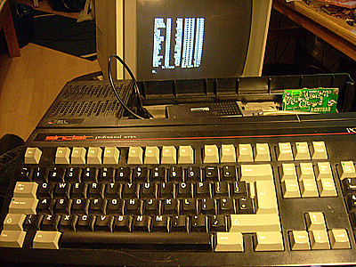
In other news, a friend of mine got a Sinclair PC 200, which is almost the
same computer as the Amstrad PC-20. He received it several years ago with a
broken power supply, and on this model the power supply also doubles as a
volume control or something like that.
He managed to convert the motherboard to take power from an AT style power
supply and manage the volume separately, but the small AT supply he found still
was too large to fit into the case.
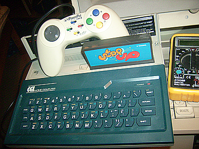
Thus, I borrowed the computer to see if it could be powered with one of
those really small supplies that one can buy from China for next to nothing.
Those are rated to deliver 5V @ 2A plus 12V @ 2A, but God knows what they
really are up to under load. At least, this Sinclair powered on and loads from
floppy disk with this type of supply, so apparently it is enough.
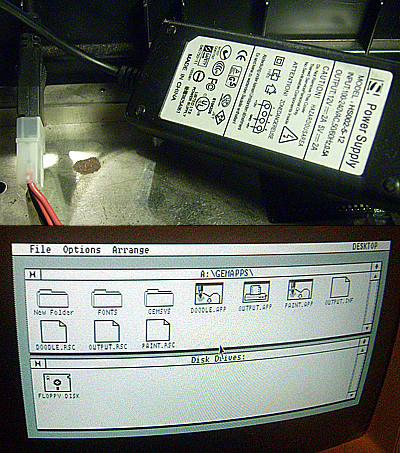
According to the specs on Old-Computers, this model supposedly has
CGA graphics but despite this monitor that I use is capable to display up to
64 colours (EGA 640x200 I suppose), during my brief testing I only got it to
display black and white.
To the right, you can see the glory of GEM a'la 1988. Now I don't have any
mouse connected to this one, so the pointer won't move anyway, but it does have
some charm.
- January 24, 23:40 (GMT+1)
-
The past few days have been mixed in the land of retro computing.
On the good hand, I managed to get ADTPro working again with the audio
interface, when connected to my desktop PC through a SoundBlast Audigy card
instead of either of those laptops I tried before. I managed to transfer a
handful of floppy images, although it takes some 12-20 minutes to download
140 kB of data.
On the bad hand, today when a gang of us gathered to prepare for an event
next weekend, my friend's Apple IIe refused to display any
meaningful picture through the RF, and we didn't have any RGB monitor at hand.
I might try to make a RGB to SCART cable later on, and have looked up the
easiest means to convert H-sync + V-sync into C-sync, which is what a SCART
cable would need anyway.
We also failed to load any software onto Oric computers, despite we tried
three different Oric-1's, one Atmos, two tape recorders and a handful of games.
It used to work, but today it did not go as planned. Some of us wasted a good
lot of time trying, swapping motherboards back and forth but to no avail.
On the positive side though, is that I finished my first (not sure if I'll
make a second, but one day I might) joypad for the Sord/CGL M5. It took quite
a bit of thinking, scratching off unwanted tracks and soldering wires to get
all four directions and two fire buttons to work. Very few M5 games use both
buttons, but since I had all wires available, I needed to make it work.
It didn't make it any easier that I screwed up which wire was which, and
spent more than 30 minutes trying to troubleshoot why fire button #2 wouldn't
register, when in fact it was wired to the wrong input. For those curious about
BASIC-G above, the fire buttons appear to be read during an $KEY interrupt
event, and the magical function is called ASW. Thus the final program to test
the joystick would look like this:
10 on joy gosub $JOY
15 on key gosub $KEY
20 joy on
25 key on
30 goto 30
40$JOY
45 rem will return 0 for joystick released, then 1, 2, 4, 8 for directions
50 J=joy(0):print J
55 return
60$KEY
65 rem could also be used to read the regular keyboard
70 K=asw(0):print K
75 return
Phew... that is something. Actually BASIC-G contains a lot of strange
statements and functions that I have never seen in other BASIC dialects.
I don't know how many of those ever got used as well, not even in Japan or
Czechoslovakia where these home computers had some kind of following.
- January 28, 01:00 (GMT+1)
-
The need for an Apple II SCART cable was not quite as immediate
as first anticipated. I began soldering up a design for a CGA to SCART cable,
but found out I had a shortage of FET transistors as used in the particular
design, so those are on back order.
Instead I spent another three hours to modify yet another PC gamepad to be
used on the M5. This time I knew exactly what to do, which speeded up the work
but I realize that I would not be able to do this mod in much less than three
hours. At least now I got a mostly matching pair of gamepads for this computer,
mostly in the meaning that I rewired the buttons differently on the second pad,
in a design that means less wires and clutter inside.